Showing posts with label Basic Electronics. Show all posts

CAPACITOR


Capacitor “OR” Condenser “OR” Filter
Capacitor is an electronic component that stores electric charge. The capacitor is made of 2 close conductors (usually plates) that are separated by a dielectric material. The plates accumulate electric charge when connected to power source. One plate accumulates positive charge and the other plate accumulates negative charge.
Electrical or electronic device that (like a battery) stores electric current for releasing it at a specific time or rate but (unlike a battery) does not generate it. Also called condenser.
Capacitors are components that are used to store an electrical charge and are used in timer circuits. A capacitor may be used with a resistor to produce a timer. Sometimes capacitors are used to smooth a current in a circuit as they can prevent false triggering of other components such as relays. When power is supplied to a circuit that includes a capacitor - the capacitor charges up. When power is turned off the capacitor discharges its electrical charge slowly.
The capacitance is measured in units of Farad (usually in microfarad [μF]).

Farad

Farad is the unit of capacitance. It is named after Michael Faraday.
The farad measures how much electric charge is accumulated on the capacitor.
There are four types of Capacitor
  1. Normal Polar Capacitor
  2. Normal Non-Polar Capacitor
  3. Micro Polar Capacitor
  4. Micro Non-Polar Capacitor
1. Normal Polar Capacitor

Symbol

Checking

Meter Set X10 and Capacitor Discharge.Meter Positive Probe Connect on Capacitor Positive Leg and Meter Negative Probe Connect on Capacitor Nagative Leg.Meter Show Reading and back Zero Reading Capacitor it's ok.
2. Normal Non-Polar Capacitor

This is used in both directions.

Symbol

Checking


Analog Meter is set x10 then Non Polar Capacitor doesn’t Reading on Meter its ok.

3. Micro Polar Capacitor

Checking

A good indication for MICRO POLAR CAPACITOR  shows the meter needle deflecting towards zero it's OK.

4. Micro Non-Polar Capacitor

Checking


A defective indication for an MICRO NON-POLAR CAPACITOR  shows that the meter will rest on zero it's OK.

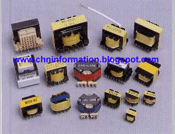
Transformer

Transformer


          A transformer is a static piece of apparatus by means of which electric power in one circuit is transformed into electric power of the same frequency in another circuit. It can raise or lower the voltage in a circuit but with a corresponding decrease or increase in current.

Buzzer

An electric signaling device, such as a doorbell, that makes a buzzing sound.


Transistor

The design of a transistor allows it to function as an amplifier or a switch. This is accomplished by using a small amount of electricity to control a gate on a much larger supply of electricity, much like turning a valve to control a supply of water. 

Transistors are composed of three parts – a base, a collector, and an emitter. The base is the gate controller device for the larger electrical supply. The collector is the larger electrical supply, and the emitter is the outlet for that supply. By sending varying levels of current from the base, the amount of current flowing through the gate from the collector may be regulated. In this way, a very small amount of current may be used to control a large amount of current, as in an amplifier. The same process is used to create the binary code for the digital processors but in this case a voltage threshold of five volts is needed to open the collector gate. In this way, the transistor is being used as a switch with a binary function: five volts – ON, less than five volts – OFF. 

Types of Transistor

1. PNP Transistor
2. NPN Transistor
3. Field-Effect Transistor

1.PNP Transistor


NPN Transistor identification in write the “A” & “B”


Checking
Meter Set X10. Meter Negative Probe Connect on Base (-) Leg and Meter Positive Probe Connect on Collector (+) Leg. Meter Show Reading Transistor OK.

2.NPN Transistor


Checking


NPN Transistor identification in write the “C” & “D”


Meter Set X10. Meter Negative Probe Connect on Base (-) Leg and Meter Positive Probe Connect on Collector (+) Leg. Meter Show Reading Transistor OK.

3.Field Effect Transistor


Checking

Step 01

Meter Negative Probe  Transistor Leg (Drain)
Meter Positive Probe    Transistor Leg (Source)

it's show reading

Step 02

Meter Negative Probe  Transistor Leg (Drain)
Meter Positive Probe    Transistor Leg (Gtae)

it's no show reading

Step 03

Meter Negative Probe  Transistor Leg (Drain)
Meter Positive Probe    Transistor Leg (Source)

it's no show reading

Step 04

Meter Negative Probe  Transistor Leg (Gate)
Meter Positive Probe    Transistor Leg (Drain)

it's show reading

Step 05

Meter Negative Probe  Transistor Leg (Drain)
Meter Positive Probe    Transistor Leg (Source)

it's show reading OK

Integrated Circuit

An integrated circuit, or IC, is small chip that can function as an amplifier, oscillator, timer, microprocessor, or even computer memory. An IC is a small wafer, usually made of silicon, that can hold anywhere from hundreds to millions of transistors, resistors, and capacitors. These extremely small electronics can perform calculations and store data using either digital or analog technology.

Digital ICs use logic gates, which work only with values of ones and zeros. A low signal sent to to a component on a digital IC will result in a value of 0, while a high signal creates a value of 1. Digital ICs are the kind you will usually find in computers, networking equipment, and most consumer electronics.


Integrated circuits are usually called IC’s or chip. They are complex circuits which have been etched onto tiny chips of semiconductor (Silicon). The chip is packaged in a plastic holder with pins spaced on a 0.1” (2.54mm) grid which will fit the holes on strip board and breadboards. Very fine wires inside the package link the chip to the pins.

Types of IC

1. SIP IC (Single Inline Package) 

2. DIP IC (Double Inline Package) 


3. PGA Chip (Pins Grid Array) 


4. BGA Chip (Balls Grid Array) 

Fuse


A fuse is a safety device to prevent excess current flowing in an electric circuit. It consists of a thin metal wire of low resistance and low melting point. When an electrical appliance or some other piece of electrical equipment becomes faulty, therefore allowing an excess electric current to flow through its circuit, this causes the wire inside the fuse to melt and thus break the flow of current. 


Fuses, by design are a one-time-use protective device - once they are used ("burn out"), they're worthless. That is why homes typically use circuit breakers: a breaker acts similarly to a fuse in that it opens a circuit when excessive current flows, but - because nothing actually melts inside it - it can then be reset without having to be replaced by a new one, as has to be done for a fuse


Fuse is a piece of wire of a material with a very low melting point. When a high current flows through the circuit due to or a, the wires gets heated and melts. As a result, the circuit is broken and current stops flowing and it’s show by “F”.


Checking

Meter set in X10 then meter one probe is fuse one side & Second probe is second side Connect.Meter show reading it's OK.

Coil Or Inductor


Coil “OR” Inductor

Working of Inductors

I Inductors are used in many analog circuits and are also used along with capacitors for forming filter circuits and thus signal processing. They are also used in Switched Mode Power Supplies (SMPS), oscillators, transmitters, receivers, voltage regulators and also for over voltage protection.

What is an Inductor?

An Inductor, also known as a reactor is simply a coil of wire, which has many electrical properties when subjected to a magnetic field. When an electric current is passed through it, a magnetic field is created. This magnetic field helps to store the electric current for a short time, even if the supply is removed. When the magnetic field around the coil collapses, the electric current also falls off.

  1. Normal Coil
  2. Micro Coil

1. Normal Coil


Symbol
Checking

Meter Set X10.Meter first Probe Connect on Coil First Leg and Meter Second Probe Connect on Coil Second Leg.Meter Show Reading Coil it's ok.

2. Micro Coil


Symbol


Checking

Meter Set X10.Meter first Probe Connect on Coil First Leg and Meter Second Probe Connect on Coil Second Leg.Meter Show Reading Coil it's ok.

Diode


Diodes allow the electricity to flow in one direction. The arrow of the circuit symbol shows the direction in which the current can flow. Diodes are the electrical version of a valve and early diodes were actually called valves.
A diode allows current to flow in only one direction.

Types of Diodes

  1. Single Diode
  2. Double Diode
  3. Full Bridge Diode
  4. Zener Diode
  5. Light Emitting diode

1. Single Diode


Diode Silver Side positive Leg & Second Side Negative Leg.

Symbol

Checking


2. Double Diode


Symbol

Checking

Step 01:

Meter Set X10. Meter Positive probe connect on Positive leg and Negative Probe Connect on First Negative Leg and Second Negative Leg .Meter Show any Reading.
Step 02:


Meter Set X10. Meter Positive probe connect on First Negative leg and Second and Negative Probe Connect on Positive Leg.Meter Show no Reading.Diode OK

3. Full Bridge Diode

Symbol

Checking

Step 01:

Meter Set X10. Meter Positive probe connect on Positive leg and Negative Probe Connect on Negative Leg.Meter Show any Reading.
Step 02:


Meter Set X10. Meter Positive probe connect on Negative leg and Negative Probe Connect on Positive Leg.Meter Show any Reading.

4. Zener Diode

Symbol

Checking

Step 01:

Meter Set X10. Meter Positive probe connect on Positive leg and Negative Probe Connect on Negative Leg.Meter Show any Reading.
Step 02:


Meter Set X10. Meter Positive probe connect on Negative leg and Negative Probe Connect on Positive Leg.Meter Show any Reading.

5. Light Emitting Diode or LED


Symbol

Checking


Meter Set X10. Meter Positive probe connect on Positive leg and Negative Probe Connect on Negative Leg.Meter Show any Reading.
\